Mission
The goal is to generate an object ground-truth pose using an RGB-D camera, a ChArUco board, and a known object CAD model or object dimensions.
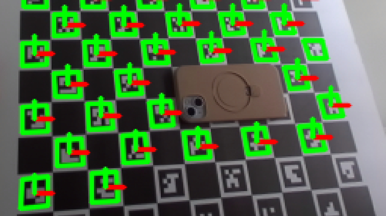
The ChArUco board gives us a stable metric coordinate frame. Once the board pose is known, the object pose problem becomes much simpler: instead of estimating the object directly in camera space, we transform the RGB-D point cloud into the checkerboard frame and fit the object geometry relative to the board plane.
Core idea
Core idea
We know:
- RGB image
- Depth image
- Camera intrinsics
- Board pose in camera frame
- Board plane in 3D
- Object detection / mask / bbox
- Object CAD model or object dimensions
The pipeline is:
RGB-D pixels → deproject to 3D camera points → transform points into checkerboard frame → isolate object points above the board plane → fit CAD/object geometry in the checkerboard frame → estimate T_checker_object
The key simplification is:
After ChArUco detection, the board plane is approximately z = 0.
So the object is no longer a mysterious 3D shape floating in camera space. It becomes a 3D point cloud measured relative to a known metric plane.
Important assumption:
The object CAD frame should be defined consistently:
- the object rests on its CAD bottom surface
- object +z points from the bottom toward the top
- the bottom of the object is in contact with, or close to, the board plane
This convention makes the fitting problem much easier because the board constrains the object’s vertical direction and support plane.
Step 1: Convert depth pixels into checker-frame 3D points
For each pixel inside the phone mask or RF-DETR bbox:
\[p_{camera} = z K^{-1} \begin{bmatrix} u \ v \ 1 \end{bmatrix}\]Then transform into the checker frame:
\[p_{checker} = {}^{checker}T_{camera} \ p_{camera}\]Pseudo-code:
1
2
3
4
5
6
7
8
9
10
11
12
13
14
T_camera_checker = pose_to_matrix(charuco_pose)
T_checker_camera = np.linalg.inv(T_camera_checker)

points_checker = []

for u, v in phone_mask_pixels:
    z = depth[v, u]
    if not valid_depth(z):
        continue

    p_camera = deproject_pixel(u, v, z, K)
    p_checker = transform_point(T_checker_camera, p_camera)

    points_checker.append(p_checker)
Now your points are expressed relative to the board.
Step 2: Use the board plane to reject background
In the checker frame, the board plane is:
\[z = 0\]Assuming your checker +z points out of the board toward the camera, phone points should be slightly above the board:
1
2
3
4
phone_points = [
    p for p in points_checker
    if min_phone_height_m < p[2] < max_phone_height_m
]
Example:
1
2
min_phone_height_m = 0.002
max_phone_height_m = 0.030
This removes a lot of clutter because anything on the board plane, behind the board, or far above the phone gets rejected.
Step 3: Fit CAD/object geometry in the checker frame
Project the filtered object points onto the checkerboard XY plane:
1
xy = object_3d_points[:, :2]
This gives the object footprint on the board.
If the object is resting on the board, do not solve full unconstrained 6-DoF immediately. Start with a plane-constrained pose:
1
2
3
4
x position
y position
z height
yaw around checker z-axis
Roll and pitch can be fixed or lightly constrained because the board plane already tells us the support surface.
The CAD fitting problem becomes:
1
Find T_checker_object such that the transformed CAD surface best matches object_3d_points.
A practical first version:
1
2
3
4
5
1. Use the 2D footprint to initialize x, y, and yaw.
2. Use median object height to initialize z.
3. Transform CAD points into the checker frame.
4. Score alignment between CAD points and observed object_3d_points.
5. Refine with ICP or local optimization.
The checker corners do not need to align with object corners. The checkerboard only provides the coordinate frame and plane. The CAD is fitted to the observed object depth points.
Pseudo-code:
1
2
3
4
5
6
7
8
9
10
11
12
13
14
15
16
17
18
19
20
21
22
23
24
cad_points_object = sample_points_from_cad(mesh)

initial_candidates = generate_plane_constrained_candidates(
    object_3d_points=object_3d_points,
    cad_points_object=cad_points_object,
)

best_pose = None
best_score = float("inf")

for T_checker_object in initial_candidates:
    cad_points_checker = transform_points(
        T_checker_object,
        cad_points_object,
    )

    score = point_cloud_alignment_error(
        cad_points_checker,
        object_3d_points,
    )

    if score < best_score:
        best_score = score
        best_pose = T_checker_object
Then refine the best candidate:
1
2
3
4
5
6
T_checker_object = run_icp_refinement(
    source_points=cad_points_object,
    target_points=object_3d_points,
    initial_transform=best_pose,
    constrain_to_board_plane=True,
)
For the first implementation, the ICP can optimize only:
1
x, y, z, yaw
instead of full 6-DoF. This makes the estimate more stable when the object is mostly planar or depth is noisy.
The fitting score can be:
\[E_{cad} \left( \min_{q \in P_{observed}} | T_{checker_object} p_{cad} - q | \right)\]where:
-
$p_{cad}$ is a sampled CAD point in the object frame
-
$q$ is an observed depth point in the checker frame
-
trimming removes large outliers from bad depth or segmentation errors
Step 4: Estimate orientation
If the object is lying flat on the board, the pose has only a few dominant degrees of freedom:
1
2
3
4
x position
y position
z height
yaw around board normal
So instead of estimating full 6-DoF freely, use:
\[R_{checker_object} = R_z(\theta)\]plus a fixed object-frame convention from the CAD model.
Example:
1
R_checker_object = rotation_about_checker_z(yaw)
If the object frame has +z coming out of the object top surface, and the object top faces the camera, then object +z should roughly align with checker +z.
This needs to match the CAD frame convention.
Step 5: Estimate translation
The fitted CAD/object footprint gives the object center in checker XY:
1
2
tx = fitted_center_x
ty = fitted_center_y
For height:
1
2
z_top = median(object_3d_points[:, 2])
tz = z_top - object_height_m / 2
This assumes the object frame origin is at the object center and checker +z points upward from the board.
So:
\[t_{checker_object} \begin{bmatrix} x_{center} \ y_{center} \ z_{center} \end{bmatrix}\]Then:
1
2
3
4
T_checker_object = make_transform(
    R_checker_object,
    t_checker_object,
)
The final output is:
\[{}^{checker}T_{object}\]This is the object pose expressed in the checkerboard coordinate frame.