Non-Destructive Testing Methods
American Society for Testing and Materials (ASTM) and American Society of Mechanical Engineers (ASME) develops standards for pipe inspections
- Ultrasonic Testing (UT)
- Standard Practice for Ultrasonic Testing of Metal Pipe and Tubing (ASTM E213-22)
- Magnetic Particle Testing (MT)
- Near-surface Notch Detection (ASTM E709)
- Radiographic Testing (RT)
- Visual Inspection (VT)
- Near-surface Eddy-Current-Testing (ASTM E2884-22)
Different liquids could cause different types of corrosions:
H2S(Hydrogen-Sulfide) creates small punctures, whereas most other liquids create relatively larger corrosions.
Major Players In The Market and Their Robot
- Features: 360 deg flip, 220 deg rotate. Front light source, backlight source, video
- $20000
- Location: Arkansas
Dilemma of ML in Pipe Inspection - Precision and Recall
Pipe inspection is labor-intensive. People don’t trust ML that much. This lies in the ML’s lower “recall” and “precision” rates
If the inspection agency missed a spot (false negative), it could bring lawsuits where we need to explain why the manual + AI system fails to detect that. In machine learning, this is characterized as “recall”.
If the system has too many false positives, then the system is too costly to verify. In machine learning, this is characterized as precision is low. In oil and gas, precision us termed as the “prove-up” rate:
\[\begin{gather*} \begin{aligned} & p = \frac{\text{verified defects}}{\text{total detected defects}} \end{aligned} \end{gather*}\]Explaining why relatively low precision and recall happens is not easy, as ML systems are still largely “unpredictable” during run-time. What’s worse is many customers and the court mistakenly think that ML systems should aim for perfect detection results, which is similar in the autonomous vehicle industry. In ML, we always compare the ML system with the “best human-level” performance.
Gas Meter
- What is LEL in Gas meter? (Lower Explosive Limit)
- Calibration: to set a baseline of “good air”. But when you calibrate it in an H2S rich environment, it’s not good
- “Unknown gas 100” can be resolved by powercycling
- Some gas meters have two modes: slow and fast
- “Zero-air” mode means clean air. If a flammable gas is detected, it can trigger an alarm.
Inspection with 3D LiDAR Examples
Sonar Imaging
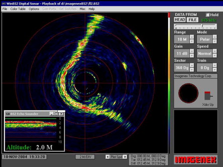
Sonar imaging cameras are able to create a 2D occupancy map or 3D point cloud.
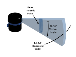
A 2D sonar scannar sends a vertical planar sound wave around 360 degrees (horizontal). It also has 1 receiver that receives the signal. If there is an obstacle, we will get a ping. It’s possible that at one fixed angle, we get multiple pings. That could be due to:
- Multiple objects being detected
- Multipath reflection taking place. This is the case where the sound wave gets reflected back to the receiver, but at a later time

How 3D Sonar Imaging Works
Here is a very helpful document on learning about the SeaBeam instruments Sonar Imaging Camera
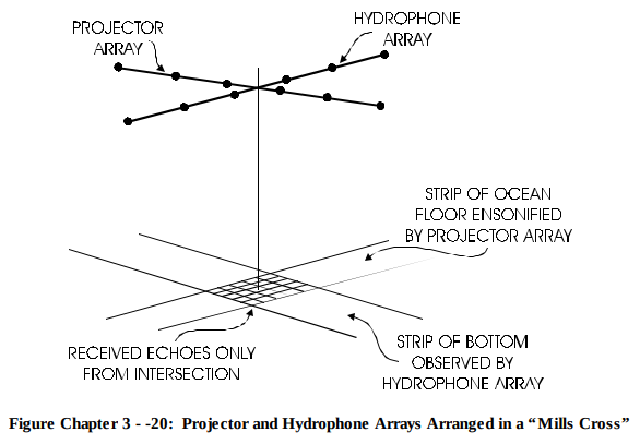
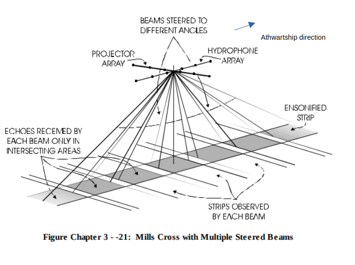
A classic “Mills-cross” setup
- Under the hull there is a transducer array—hundreds-to-thousands of ceramic (piezo) elements laid out in a line (or sometimes two lines). The transducer creates a ping
-
Each ping goes to a projector array, which carefully applies delays (or phase shifts) to every element so the individual wavelets add up in a chosen direction and cancel elsewhere. (Constructive and Deconstructive Interference, Similar to Phase Array Radar). The output wave looks like a fan:
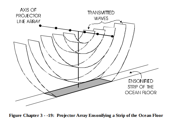
- A receiver (hydrophone) array
- After the ping, each patch of the sea bed sends back a plane-wave (to very good approximation). Each receiver receives them and could form their own waveform: $A(t)$ (amplitude), and $\phi(t)$ (phase)
- The receive array is at most a few metres long; the covered seabed distance (swath) is hundreds of metres away.
- We assume the distance from the camera to sea bed is much longer than the receiver array size (far-field condition):
Range >> L^2/lambda. A single echo from the seabed will have an arbitrary angle of incidence $\theta$ on to receiver 3, 2, 1. It will first reach 3, then travel by $d sin\theta$ to 2, then $d sin\theta$ to 1.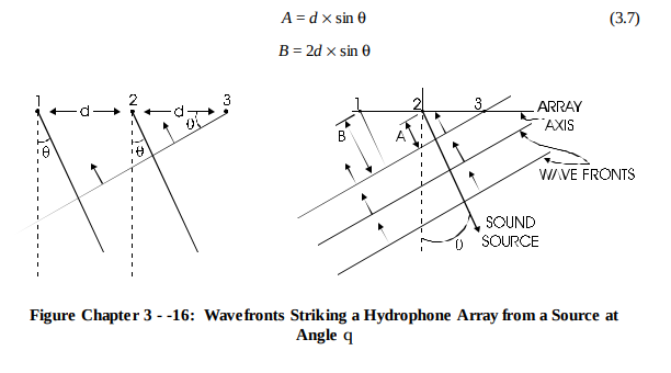
- the spherical wavefront that leaves any single patch is practically planar by the time it spans the array. Therefore,
-
So effectively, we can work out the beams to each patch of the seabed, based on the received waveforms at each receiver
- After the ping, each patch of the sea bed sends back a plane-wave (to very good approximation). Each receiver receives them and could form their own waveform: $A(t)$ (amplitude), and $\phi(t)$ (phase)
Gradian
In fields like surveying, you have small angle calculation. 460 deg = 400 gradian - use gradians because they’re easier for decimal math, but that’s about it. For example, in gradians, 90 degrees = 100 gradians.