🧪 Loop Detection Testing Procedure
Phase 1: Baseline Verification (No Loop Closure)
Objective: Confirm that submaps are constructed correctly before enabling loop closure.
Steps:
- Disable loop closure module.
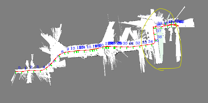
- Run SLAM and verify that submaps are:
- Existent
- Aligned well locally
- Free of noticeable drift in short-term movement
Phase 2: Setup for Loop Detection
Objective: Prepare the system to test loop detection with minimal data.
Steps:
1
2
1. Configure submap lifetime settings (e.g., number of frames/submaps kept in memory) so there are at least two submaps
2. Ensure both submaps cover overlapping or loop-closure-worthy regions.
Phase 3: Loop Closure Trigger and Validation
Objective: Run the full loop closure pipeline and validate each stage.
- Add Data
- Add a new submap (e.g., return to origin or overlap with earlier area).
- Add a new keyframe that observes previously seen area.
- Trigger Backend Optimization
- Manually or automatically trigger the optimization pipeline.
- Loop candidates should be detected.
- Check logs or visualizations to confirm a loop is recognized.
- Manually or automatically trigger the optimization pipeline.
- Matching Against Historical Submaps
- The current keyframe should match a submap from history.
- Ensure a match score is above threshold and transformation is plausible.
Issues Encountered Along The Way
🔍 Why is the scan alignment poor?
The scan alignment appears poor likely due to motion distortion. Motion distortion causes lidar points to spread out or “disperse” unnaturally because they are captured at different poses during motion. This leads to misaligned features in the scan, making scan matching unstable or inaccurate.

🧭 Why skipping a distorted frame might not help
Even if we skip a distorted frame, there’s no guarantee that the next frame will match correctly either:
- If subsequent frames fail to match, it can break the odometry chain.
- This causes missed loop closures and loss of trajectory continuity.
💡 Possible Solutions
- Use IMU Data: IMU can help find the motion updates for a latter subsequent scan
- You can transform each point based on the estimated pose at its exact timestamp.
- This realigns points into a consistent frame, significantly improving scan integrity.
- Use CT-ICP (Continuous-Time ICP): Rather than estimating a single rigid transformation between scans, CT-ICP accounts for motion during the scan:
- Model the platform’s trajectory as a continuous function of time (e.g., cubic B-spline).
- Transform each lidar point using the pose at its timestamp.
- Optimize the continuous trajectory while aligning points to a map or previous scan.
- If software solutions aren’t feasible, consider reducing distortion at the source:
- Lower the vehicle speed: Reduces motion between the start and end of a scan.
- Increase lidar RPM
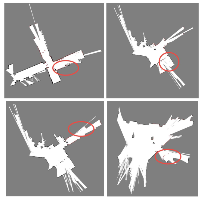
These scans are distorted in different ways:
- Top left: motion distortion
- Top Right: Transmission of light (Inherent Limitation)
- Bottom Left : Reflection (Normally they will be eliminated in data post processing, Inherent Limitation)
- Bottom Right : Tilting Platform (Inherent Limitation)
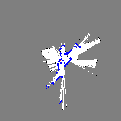
Degenerated case where there’s large empty space:
Optimize Using Close Scan Lines and Angles
- THESE TWO LINES ARE INCREDIBLE - THEY MADE A HUGE DIFFERENCE!!
1
2
3
4
if (scan_obj.range > range_th) return;
if (scan_obj.angle < -2.35619 + 30 * M_PI / 180.0 || scan_obj.angle > 2.35619 - 30 * M_PI / 180.0) {
  return;
}
Bicubic Is Not Necessarily Better Than BiLinear? TODO
Vulnerabilities
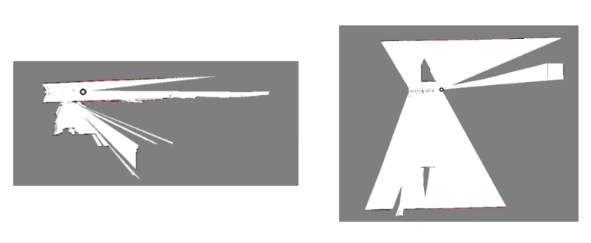
[1] Range threshold for optimization is too short.
Scan matching fails in a semi-degenerated scenario:

Consecuently, the same hallway appears in the wrong position
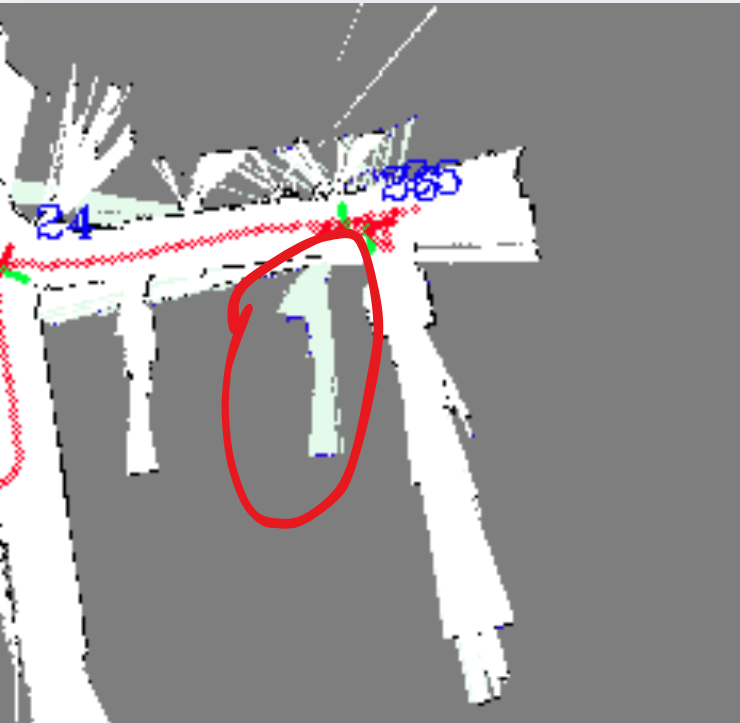
If loop detection is weak, this may not be corrected. E.g., If the submap distance threshold is too short, so loop detection wasn’t triggered - What happens next is subsequent scans are skewed