There are two types of GNSS:
- Traditional single-point GPS: 10m accuracy, usually found in phones.
- Lat-long is a.k.a geographic coordinate system
- Differential GPS (DGPS). One example is RTK (Real-Time-Kinematics) GPS. centimeter accuracy. It talks to a base station. Each module gives its
(x, y).- Single RTK unit with two antenna ports is a common solution. You buy a dual-antenna RTK receiver module (it has two coax inputs) and mount your two GNSS patch antennas with a known baseline separation. The receiver itself measures the relative phase delay between the two antennas on the same clock, so it can instantly compute a very accurate heading (carrier-phase differential) down to centimeter-level baselines.
- Both antennas see the same satellite signals on the same carrier frequency.
- The receiver measures the phase delay between antenna A and antenna B for each satellite.
- Baseline length must be known - the vendor asks for it as an initial value to solve for the Phase count. Without it phase count would converge more slowly. That phase delay can be turned into a vector direction in space—i.e. the heading of the baseline.
- If you use two separate RTK receivers (each with its own antenna) instead, you’d have to:
- Synchronize both receivers to the same timebase (so you’re comparing measurements from the exact same epochs),
- Calibrate their inter-antenna vector in post (each has its own small internal antenna offset and antenna-phase center)
- Coordinate system: we use east-north-sky. But some manufacturers of the GPS may use north-east-earth
- Single RTK unit with two antenna ports is a common solution. You buy a dual-antenna RTK receiver module (it has two coax inputs) and mount your two GNSS patch antennas with a known baseline separation. The receiver itself measures the relative phase delay between the two antennas on the same clock, so it can instantly compute a very accurate heading (carrier-phase differential) down to centimeter-level baselines.
GPS
A GPS needs to talk to at least 4 satellites to run a trillateration process to determine its current pose.
A GPS module’s performance is affected by:
- Atmospheric delay: signals can be delayed as they pass through the ionosphere and troposphere.
- Multipath errors: signals can bounce off surfaces like buildings or mountains
- Satellite geometry: misalignment of satellite can reduce accuracy
A consumer grade GPS is 10m accuracy 95% of the time
0 deg meridian is a line that runs through Greenwich. 180 deg meridian is a line runs from North to the south pole. $It goes through Chukotka$
Fix: is the process navigation satellites -> position, velocity, time.
- ROS2’s
sensor_msgs::NavSatFixhas no heading field. The best way to pass GPS messages around is to create your own message type
RTK GPS Modes
RTK refers to 载波相位差.
- Single point:
- No base station is connected.
- floating point rtk:
- Uses GPS -> base station, but phase number is unresolved and is represented as floating point? Its accuracy is ~0.5m. It’s an intermediate solution between single and fixed point
- Fixed point RTK
- Need at least 5 satellites
- accuracy is <0.1m
How GPS Trilateration Works
Given:
- Four satellites with known positions $ \mathbf{S}_i = $x_i, y_i, z_i$ $ for $ i = 1, 2, 3, 4 $,
- Measured distances $ r_i $ from receiver to each satellite. We want to find the unknown receiver position $ \mathbf{x} = $x, y, z$ $.
For each satellite, we have: \(\|\mathbf{x} - \mathbf{S}_i\|^2 = r_i^2.\)
Subtract satellite 4’s equation from others: \(\|\mathbf{x} - \mathbf{S}_i\|^2 - \|\mathbf{x} - \mathbf{S}_4\|^2 = r_i^2 - r_4^2.\) Expanding and simplifying:
\[2(x_4 - x_i)x + 2(y_4 - y_i)y + 2(z_4 - z_i)z = r_i^2 - r_4^2 - \left[(x_i^2 - x_4^2) + (y_i^2 - y_4^2) + (z_i^2 - z_4^2)\right].\]This yields a linear system: \(A \mathbf{x} = \mathbf{b},\)
where:
- $ A \in \mathbb{R}^{3 \times 3} $ has rows $ 2(\mathbf{S}_4 - \mathbf{S}_i)$,
- $ \mathbf{b} \in \mathbb{R}^3 $ is the simplified right-hand side.
If overdetermined or noisy, solve using the pseudoinverse: \(\hat{\mathbf{x}} = A^\dagger \mathbf{b}.\)
This gives the least-squares estimate for the receiver’s position.
RTK GPS
RTK (Realtime-Kinematics) GPS needs an extra ground station that sends correction data to itself. The general workflow is:
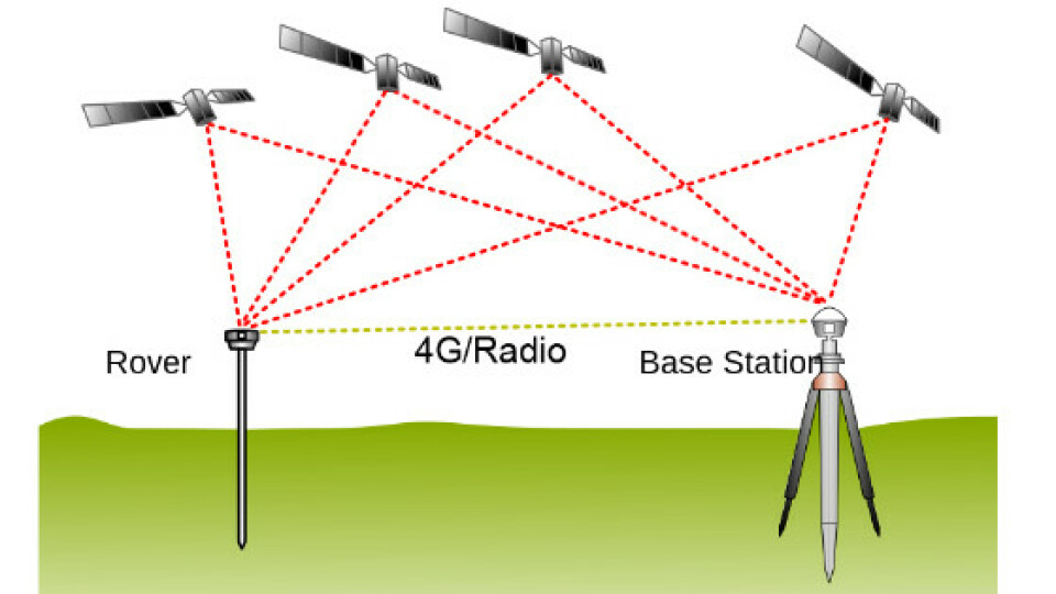
- A GPS Ground stateion is a known location. Its location is determined during a survey-in
- The GPS ground station gets its GPS reading from the 4 satelelltes through trillateration. Each satellite starts broadcasting a message that’s received by the base station and rovers.
- The base station broadcasts a satellite message. A nearby RTK-GPS rover (<10km>) hears it, and calculate correction factors
- It’s called RTK because correction factors are calculated as the model moves (“kinematics”)
Correction Factors
Modelling
\[\begin{gather*} \begin{aligned} p = r + c(\delta t_u - \delta t^{(s)}) + I + T + \varepsilon_p \\ \varphi = \lambda^{-1} \left[ r + c(\delta t_u - \delta t^{(s)}) - I + T \right] - N + \varepsilon_\varphi \end{aligned} \end{gather*}\]- $p$: Pseudorange observation (meters).It’s the
c * apparent_time_difference- So the formula basically says “the pseudorange is the sum of the true satellite-receiver distance, clock bias (difference), and various delays”
- $r$: True geometric distance between satellite and receiver (m)
- $c$: Speed of light (m/s)
- $\delta t_u$: Receiver clock bias (s)
- $\delta t^{(s)}$: Satellite clock bias (s)
- $I$: Ionospheric delay (m)
- $T$: Tropospheric delay (m)
- $\varphi$: Carrier-phase observation (in cycles or radians)
- $\lambda$: Carrier wavelength (m)
- $N$: Integer ambiguity (in cycles)
- $\varepsilon_p$, $\varepsilon_\varphi$: Measurement noise or unmodeled error
The observation equations include aggregated error terms $\varepsilon$, representing unmodeled effects. For simplicity, these terms are omitted in subsequent formulas.
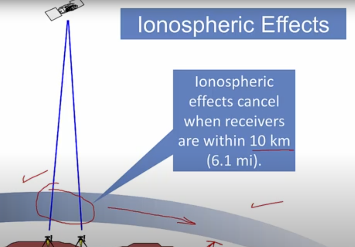
In step 2, ionospheric effect could cause delays experienced by receives and base stations. If a rover is close to a base station, the ionospheric delay is roughly the same:
Single-, Double-, and Triple-Difference Observation Equations
The base station sees: - Apparent time (a.k.a pseudo range) - $t_{true} + t_{delay}$ - Phase: (see below)
At the rover side, by taking the difference between the satellite message it hears directly and that from the base station, the resulting single-difference observation is:
\[\begin{gather*} \begin{aligned} p_{ij}^p = r_{ij}^p + c \delta t_{u,ij}^p \\ \varphi_{ij}^p = \lambda^{-1} \left( r_{ij}^p + c \delta t_{u,ij}^p \right) - N_{ij}^p \end{aligned} \end{gather*}\]- Subscripts $i$, $j$: Receiver indices for the rover and satellite
- $p_{ij}^p$: Single-differenced pseudorange
- $\varphi_{ij}^p$: Single-differenced carrier-phase
- $r_{ij}^p$: Single-differenced geometric distance
- $\delta t_{u,ij}^p$: Single-differenced receiver clock error
- $N_{ij}^p$: Single-differenced integer ambiguity
Carrier Phase and Wavelength Counts
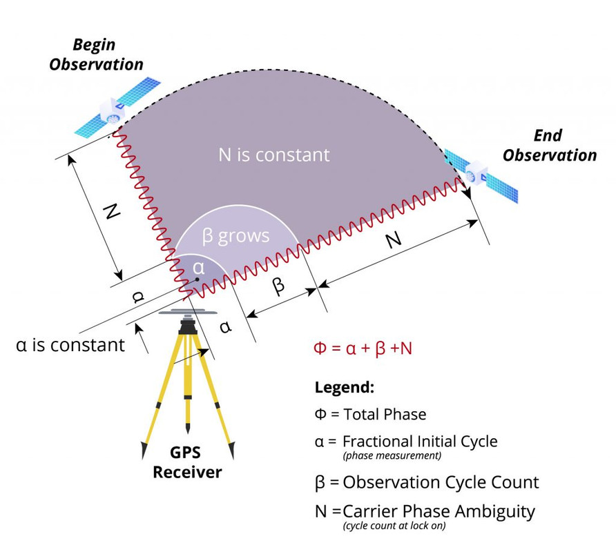
Another crucial technique RTK GPS uses is Carrier Phase Ambiguity resolution. The carrier wave is a high frequency sinusoidal wave. In the illustration below, we can determine the distance between a satellite and a rover using the number of phases. Here, the total number of wavelength is $\phi = \alpha + \beta + N$. We aim to solve for N:
N: an integer that represents a fixed number of wavelengths. This number is unknown at the moment- The L1 carrier wave is transmitted at 1575.42 MHz, its wavelength is 19cm.
- $\alpha$ is the fractional number of wavelengths. E.g., if the total distance is in total 10.5 wavelengths. $\alpha = 0.5$
- $\beta$ is the “accumulated number of observed wavelengths during the measurement period.” As the receiver moves and the satellite orbits the earth, $\beta$ shrinks when the two gets closer, and expands when the two gets farther apart.
RTK GPS in Autonomous Vehicles
In an autonomous vehicle, we use two RTK GPS modules (蘑菇头) so we know the mid point (x, y, z), and its heading $\theta$. This set up is also known as DUAL GNSS Compassing. Usually, GPS signals come in at 1hz.
There are three ways to mount the RTK. The angle between the line and the heading of the car is an “extrinsic rotation”:
Longitude - Latitude System
Longitude and latitude is a very well-known concept. Some drawbacks are:
- Requires many significant digits to represent a location precisely
- Not directly in meters
- The polar areas have a singularity, because longitude
0 - 180 degconverges there. So any longitude value could be assigned to the north pole, but in the meantime, large changes in the longitude would happen, too.
UTM Coordinates
The Universal Transverse Mercator (UTM) coordinate system can better handle the significant digits issue better.mercator is a projection method that projects a globe onto a cylinder

UTM uses the Transverse Mercator projection. It’s not the “normal” Mercator <div style="text-align: center;">
</div>
Latitude limits: 80 ° S to 84 ° N. The UTM system is defined only between 80 ° S and 84 ° N (not exactly ± 80 °). Beyond those latitudes the Universal Polar Stereographic (UPS) system is used instead.
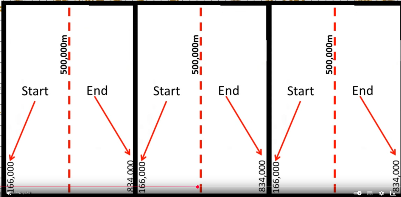
Each zone’s central meridian is assigned a “false easting” of 500 000 m so that all easting values within the zone are positive. That does not mean the zone is 1 000 000 m wide—actually at the equator 6 ° ≃ 667 000 m, and the easting values of each cell typically starts from 166 000 m to 834 000 m depending on the exact longitude.
Along the central meridian the projection scale is 0.9996 (so distances there are 0.04 % too small), and it increases toward the zone edges (up to about 1.0004). That scale factor is dimensionless (it multiplies lengths), not “0.9996 m per meter.”
Easting and northing in metres A UTM coordinate is simply “Easting, Northing” in metres from the false-origin (500 000 m E at the central meridian; 0 m N at the equator in the northern hemisphere, 10 000 000 m N at the equator in the southern).
Workflow
- Projects the globe onto a map
- Segment the map into 60 parts (longitude) and 20 parts (latitude).
- Each zone is 6 deg longitudinally, 8 deg latitudinally. They are numbered eastward from 180 ° W
- Each zone spans 6 ° of longitude. Zone 1 runs from 180 ° W to 174 ° W, zone 2 from 174 ° W to 168 ° W
- The 20 latitudes are represented by a letter in
C to X, exludingIandO- Zone
33Trepresents zone33in the T latitudinal region
- Zone
- Each zone is 6 deg longitudinally, 8 deg latitudinally. They are numbered eastward from 180 ° W
- Each zone has a coordinate frame
x = left = east, y=up=norh - The center line is x = 500km
- UTM has opposite north directions in the southern hemisphere
Advantages:
- Directly in meters!
- Fewer sigificant digits are required
500kmis a common scale requires 6 significant digits. So to represent centimeters, one needs 8 significant digits (FP64)
Drawbacks include:
- Region number are required in representation
- So cross-zone operations should be handled separately. But some RTK systems help us handle this.
- Distortions are large in the polar zones